
The use of model-based design to develop embedded software is well established in automotive projects but with the growing size and complexity of software, handling big sized model is often a challenge. Model-based design enables to easily craft a software application and from one step to another refine it, test it and generate the production code. However, jumping into the modeling without a software architecture is a risk. It’s impossible to develop an automotive software application as one single function due to the complexity, the software architecture therefore introduces a modular approach. In ISO 26262, software modularity is addressed with the principle of “Hierarchical structure of software components”. In this article, we’ll see how to apply this principle in Simulink using the component-based modeling for efficient software development and testing.
First of all, let’s start with some definitions.
What is a software architecture?
Defining the software architecture is an important step to ensure an efficient development of complex software.
Example: A software application can be modeled for Rapid Prototyping without a detailed software architecture definition but later in the development process, testing a piece of the software in Software-In-the-Loop (SIL) will be impossible if the corresponding function is not present in the production code.
More generally, the software architecture describes the elements that constitute the software as well as their interactions. This includes the definition of static aspects starting from the hierarchical structure of the software, executable functions, interface variables, datatypes, etc. It also defines dynamic aspects such as execution modes/timing/order, temporal constraints, etc.
In many projects we observe that the notion of software hierarchy is present but the definitions are not standardized. We often hear terms like “Module”, “Feature”, “Function”, “Unit”, “Component”, “Application”, etc. but from one project to another, they are used completely differently. In the AUTOSAR standard for instance, there are three levels of hierarchy with standardized definitions: Composition, Atomic Software Component and Runnable. The Runnables are the executable software entities and the Atomic Software Component and Composition are encapsulation levels. In the ISO 26262 standard we see two terms: Software Components and Software unit. The Software unit is considered as the lower level piece to design the software and a Software component gathers one or multiple Software units in an encapsulation fashion. Independently of the terms that are used, the concept behind a hierarchy of dependencies shall be clearly defined in the organization. Nevertheless, if the project has to comply with a standard, it’s recommended to use the same definition and wording of the standard. In this article, we’ll illustrate the topic of component-based modeling using the terms of the ISO standard: Software component and Software unit.
To design the software architecture, a dedicated tool should be used. For an AUTOSAR architecture, it makes sense to use an AUTOSAR authoring tool as it offers the necessary features for this rich standard but in general, professional software architecture tools offer sufficient features and abstraction to design the architecture. For more efficiency in the model-based context, it’s better if the tool can integrate with the model-based environment.
What’s a software unit?
According to ISO 26262, a software unit is an atomic level of a software component that can be subject to standalone testing. One or more software units constitute a software component.
Characteristics of a software unit
- It can be designed, implemented and tested separately, independently of the remaining software.
- It implements a well-defined set of requirements with bi-directional traceability.
- It’s independent in a way that it can be implemented by one single developer
- It has a high self-cohesion: it’s atomic, focuses on one functionality and its dependencies to other units is reduced to well defined interface variables.
- It can be reused across multiple software applications.
Size and complexity
There are no systematic ways to define the ideal size of a unit (e.g. in terms of numbers of blocks/signals in the model-based context) but the ISO standard for instance recommends to restrict the size of software components, the number of interfaces and describes methods to reduce the complexity. In general, we can say that the size and complexity can be balanced between three aspects:
- From the perspective of the function developer/tester, it shall be possible to analyze and understand the allocated set of requirements.
- The functionality itself: an appropriate algorithm shall be chosen to implement the function considering that embedded software is a limited world. (e.g. the ideal mathematical solver cannot always be chosen).
- Smart coupling: Highly dependent functionalities shall reside in the same unit as much as possible while decoupled features shall be split into different units. (e.g. preparation for software partitioning and criteria such as freedom-of-interference)
- Guidance of technical criteria: metrics from complexity analysis tools, hardware resource consumption limits, software partitioning (e.g. for freedom-of-interference), etc.
Structuring the software architecture in model-based environment
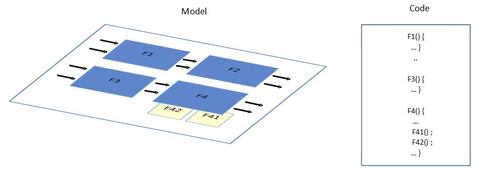
In Simulink, a software component can be designed in one model. The model is structured using subsystem blocks. A subsystem gathers a subset of functionalities usually derived from the software requirements. Simulink subsystems can be virtual and non-virtual (aka atomic). Virtual subsystems are mainly meant for readability/traceability and reduction of visual complexity while atomic subsystems, in addition to that, have an influence on the behavior: the content of a non-virtual subsystem is executed all at once. Therefore, non-virtual subsystems are suitable to model software units thanks to their atomic nature. Defining an atomic subsystem will:
- reveal unwanted dependencies to the remaining model like algebraic loops, external events signals crossing the unit boundaries, etc.
- guarantee the atomic execution of the subsystem operations in the generated code
- enable to generate the subsystem as an individual c-function.
Within an atomic subsystem that represents a software unit, it’s also possible to have smaller atomic subsystems for inner implementation purposes like conditional execution parts, reusable functions or to split the unit into smaller functions in the generated code for resource management.
Ultimately, the resulting structure of the software component model is composed of horizontal and vertical hierarchies where subsystems are interfaced via data and control signals.
Although one model can represent the hierarchical structure of a software component, this model cannot easily support further development aspects like distributed development, maintainability, reusability, testability and integration of the individual software units because the scope of pure subsystem blocks is limited to the model.
Simulink component-based modeling using Library blocks or Model references
Simulink supports a “component-based” modeling style allowing to segment a model into separate and independent models which can be integrated together via reference and link mechanisms. With this approach, each model can represent a software unit and be designed, simulated and tested individually. The integrated model can thus represent the software component. Two techniques can be used for this purpose and here are their main characteristics:
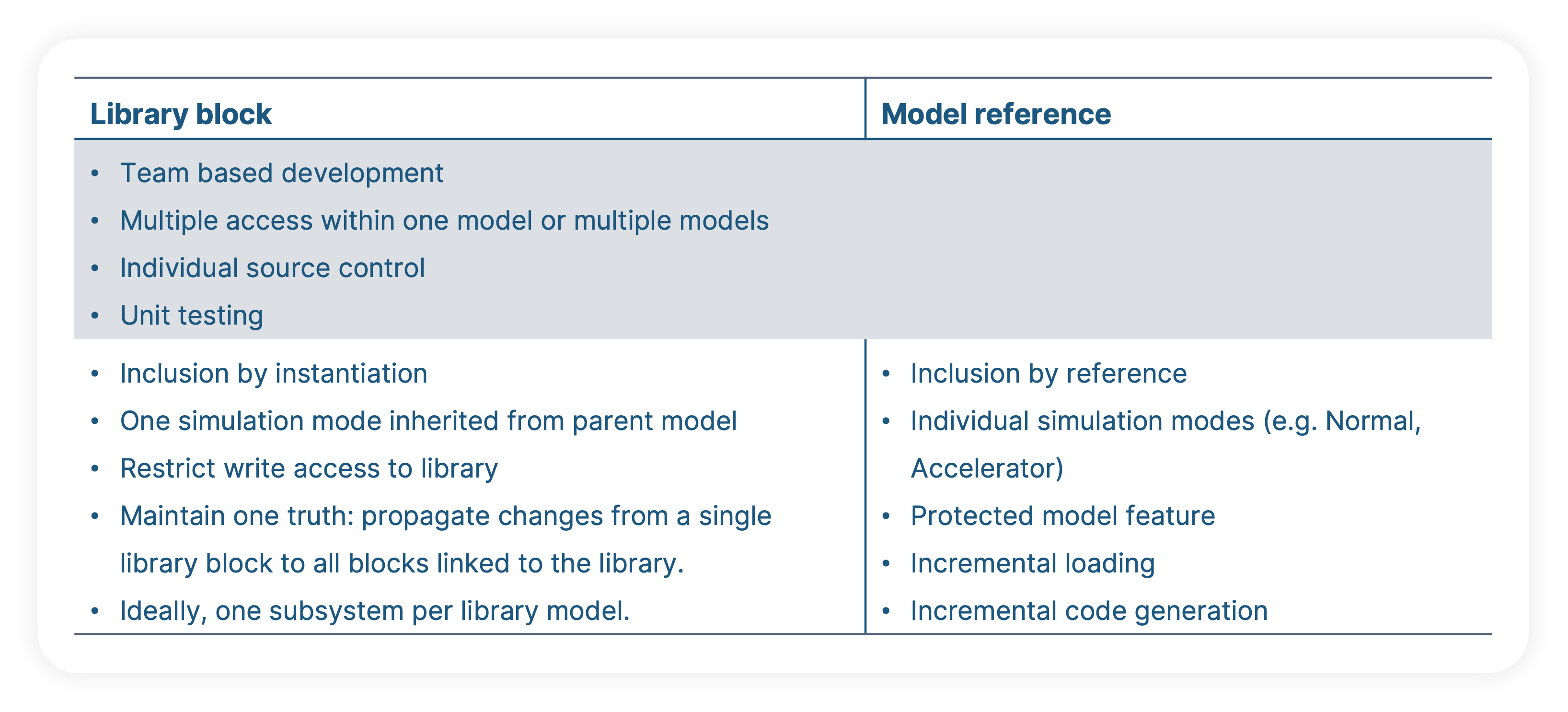
Each technique or both combined can be applied for component-based modeling. Furthermore, a folder structure can be defined to organize the different models and synchronize the files with the software configuration management tool for versioning, etc.
Note: The reference between the software unit models and the models of higher architecture levels can use either of one the two techniques (Library or Model reference). With the library option, the software unit is an atomic subsystem block stored in a library model and the frame model instantiates the Subsystem block. With the Model reference option, the software unit is the model itself and the frame model uses a Model block to reference it.
Unit and integration tests in the modular structur
The test methods recommended on unit and integration levels are pretty similar as described in the ISO standard. For instance, Requirements-based testing can be carried on the unit and integration models but the granularity of the requirements is not the same. On the integration level, the requirements will talk about more high-level behavior of the system while on unit level they will describe the algorithm details. Therefore, the test quality criteria on both levels are different. Unit tests shall verify that there’s no unintended functionalities by looking at the metrics of requirements coverage and structural coverage “Statement”, “Branch” and “MC/DC”. Integration test mostly looks at the requirements coverage and also addresses “Function” and “Function Call” coverage.
Note: Before performing the integration tests, the software units shall be sufficiently tested to increase the confidence on each unit so the problems occurring during the integration would most likely be reduced to the scope of the interaction between the units and not individual malfunctions.
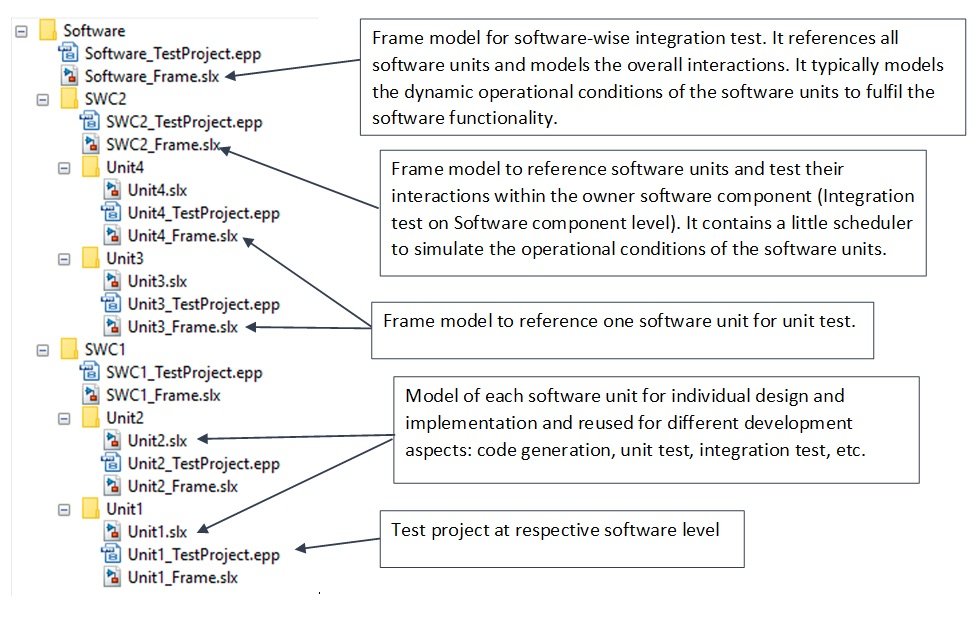
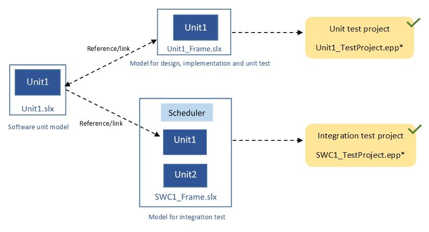
The modular structure of the models and the relationship between models and test projects can be illustrated as follow:
With this modular structure, it’s easier to manage the complexity. Software units can have relatively small size. They can be designed and tested individually. Code generation, test execution and debugging are faster making the development iterations more agile. Automatic test generation for test methods like Back-To-Back Test perform much better on smaller units. Moreover, when requirements change, only the corresponding model needs to be updated. All these make the approach highly suitable for agile-based software development. However, it’s worth to emphasize that defining a fine granularity of the software architecture requires additional effort in early project phases, for instance to break down the high level requirements but this effort gets highly rewarded throughout software development cycle.
Conclusion
The component-based modeling of Simulink allows to handle large software models by breaking the model down to smaller ones. Each smaller model can represent and fulfill the characteristics of a software unit. The software development is performed on the software unit models and these models can be assembled via sophisticated reference mechanisms to support the remaining activities like integration test at higher level. The reference mechanism allows to keep the referencing models up-to-date in regards to the referenced model. Hence, testing can be performed on unit and integration levels and always execute the original software unit.
The decomposition of the software architecture is not always effortless but in the end, the resulting modular architecture enables to successfully manage software complexity and increases the efficiency of the development process throughout the software life cycle.
It is technically possible to convert an existing large model into component-based models but it’s usually a time-consuming task (e.g. model restructuring, introduction of new interface variables, fixing algebraic loops, performing regression test, etc.). It shouldn’t be a standard and systematic workflow but may be needed in the context of a one-time process change.