
In Model-based Development and Embedded Software Engineering, the growing complexity requires concepts like modularization, ease of maintenance, or module reusability. In this context it is crucial to understand the interface in Simulink, which is defined by the data flow into and out of a subsystem. This blog article gives an overview about the different interfaces and Simulink data flow options and the effect on code generation and testing for embedded applications.
Visible data flow via Ports
Well-defined interfaces are an integral part of a modular design. Commonly a Simulink subsystem communicates with the rest of the model via inports and outports. Every port is characterized by a data type (e.g., UInt8 or double) which can be either specified explicitly in the block dialog or inherited from the signal source. In the latter case, the data type can be displayed next to the outgoing line of the block, once the model has been initialized (e.g., via the command Control+D). In addition to scalar variables, a port can also contain more complex information in form of vectors or multi-dimensional arrays.
As a Simulink model grows in size and complexity, a large number of inports and outports can be difficult to organize and edit. One way to overcome the visual clutter is to group the signals in form of Buses. Simulink blocks such as Bus Creator and Bus Selector will help the user to group the signals and select the signals that are of interest. One bus signal can also contain other buses, allowing a hierarchy with several levels. Providing signal names will help the user to identify the signals in later stages. It is also possible to group buses into an array of buses.
Simulink buses can be either virtual or nonvirtual. The main difference between virtual and nonvirtual buses is how the memory allocation is done in Simulink. The virtual bus is a virtual representation, and it doesn’t affect how the memory is allocated, whereas a nonvirtual bus represents memory.
Following image summarizes a model with virtual bus connected to a virtual subsystem and a nonvirtual bus connected to a nonvirtual subsystem.
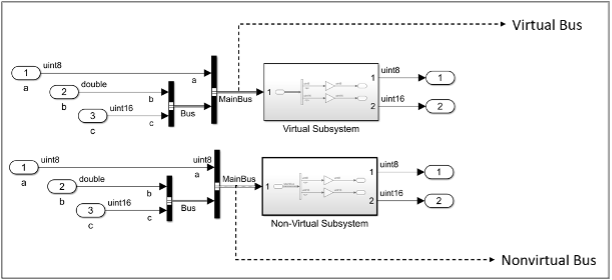
Within the generated C-Code, only the components within the bus that are utilized within the subsystem are passed through the boundary. i.e., there will be no proof within the code that other signals also entered the function. At compile time, a direct connection between ports replaces the virtual bus. For nonvirtual bus, the input signal is copied into a variable, which uses structures with a shorter interface and the structure matches the bus object definition. The concept of defining an interface using a bus object is carried through to the generated code.
While buses can make a complex model “easier to read”, they can also hide information as the effective interface of a subsystem might not be visible (“effective” meaning the signals which are actually used inside of the subsystem). A possible solution is, to put the needed bus selectors outside of the subsystem and therefore only provided the needed signals on the inports.
Hidden data flow between scopes
Until now we only talked about signal flow represented by signal lines. However, constructs like [GoTo]/[From] and Data Store Memory blocks enable passing information throughout the model without a direct line connection. We can call this “hidden data flow” because the data can cross subsystem boundaries without being visible as explicit lines and ports.
GoTo/From Blocks
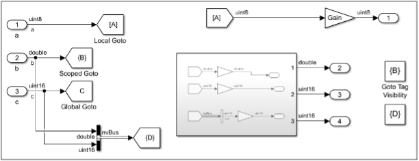
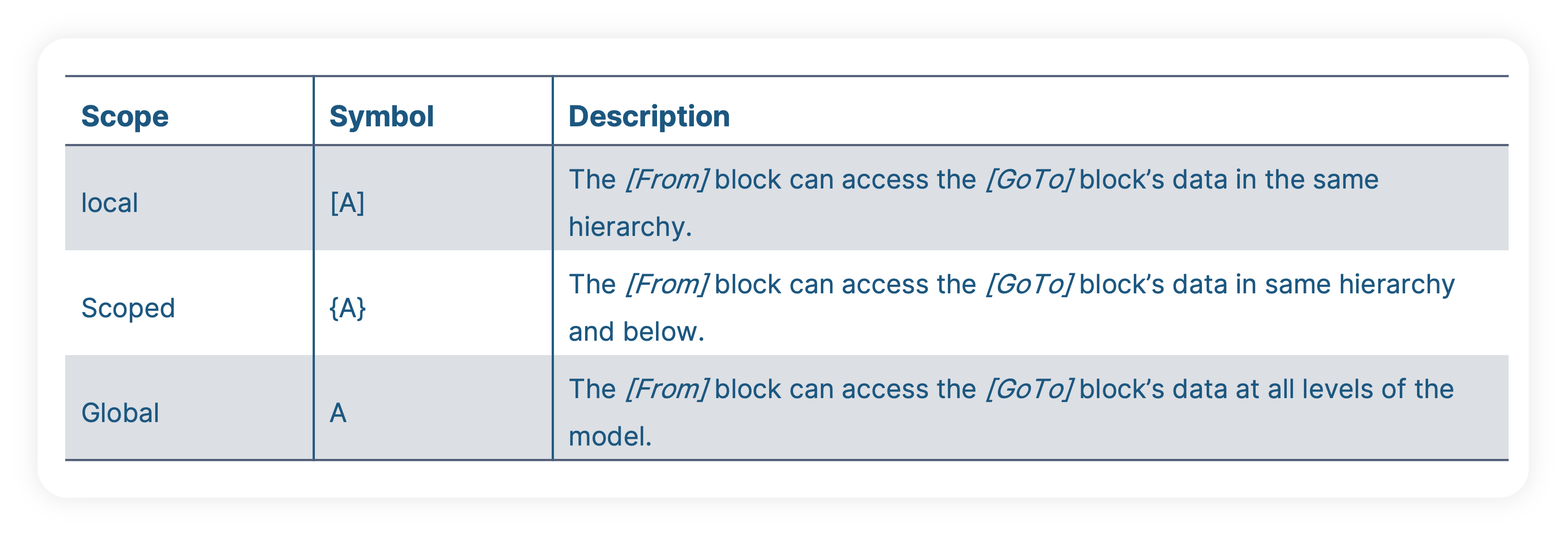
[GoTo] and [From] blocks allow for the signal connections to be made without a direct connection between blocks. The data passed into a [GoTo] block can be called by all corresponding [From] blocks. A single [GoTo] block can have more than one [From] blocks. It also possible to pass the bus signals across the subsystems using a combination of Buses, [GoTo] and [From] blocks. The accessibility of the [GoTo] block data by a [From] block depends in the [GoTo]block’s tag visibility. The permitted scopes are:

For auto code generation, we have to distinguish between virtual and non-virtual subsystems. For a virtual subsystem, the C-Code is not affected by the use of from/goto blocks. If the subsystem is nonvirtual, initializing the system runs into compilation error because [GoTo]/[From] connections cannot cross nonvirtual subsystem boundaries.
According to the MAAB guidelines, rule na_001 suggests that [GoTo] block scope shall be set to Local. When [GoTo]and corresponding [From] blocks are used across subsystem boarders, the connection relationships can be difficult to understand, and errors can also occur when the configuration of a subsystem changes from virtual to nonvirtual.
MAAB rule Jc_0171 also suggests using at least one signal line between two structural subsystems. i.e., to not have floating subsystems such as all inputs/outputs connected via [GoTo] and [From] blocks.
Data Store Memory
A Data Store is a named memory in Simulink. Data Store Read and Data Store Write blocks of the same name can access the Data Store Memory block. This means that the Data Store mechanism also enables the data transfer between the subsystems without a signal connection using ports. When the Data Store Memory block is defined in a subsystem, Data Store Read and Data Store Write blocks can access the block only if they are located in the same hierarchy or below. Another option which doesn’t need a Data Store Memory block is a global Data Store defined as a Simulink.signal object in the workspace which allows all the Data Store Read and Data Store Write blocks to access the data by all models in the Workspace. Similar to [GoTo] and [From], multiple Data Store Read and Data Store Write blocks can be used for one Data Store memory block or Simulink.signal object. However, this can introduce issues with the order of access to a Data Store. There are three defined order of access errors associated with Data Stores:
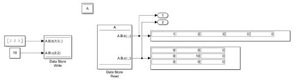
Starting from MATLAB 2011 version, Data Store blocks also provide Bus support. The following image shows as example of using Bus objects in Data Store memory blocks.
MAAB rule jc_0161 suggests defining the Data Store Memory block with data required for code execution and generation and to define the Data Store Memory block in the smallest possible scope. This improves the readability when the usage is limited, and the unused data can affect the maintenance and operability.
MAAB rule na_0024 suggests using signal lines between MATLAB function instead of Data Store blocks. When multiple Data Store blocks are used, they reduce the readability of the data flow, leading to errors in update reference timing.
Conclusion
For complex models, it can become difficult to understand how the different communication mechanisms contribute to the architecture. This article described different interface concepts of Matlab/Simulink models as well as their impact on readability and automatic code generation.
When it comes to testing the models, we can first say that the used test tools need to be able to deal with all these interface concepts in order to connect their test harnesses to the model. When it comes to writing the test cases, it is of course important for the test engineer to understand the effective interface of the subsystems. This can be challenging when the effective interface of a subsystem is not directl visible, e.g. because of unused bus signals or Data Stores.